Cantilever Gate Systems
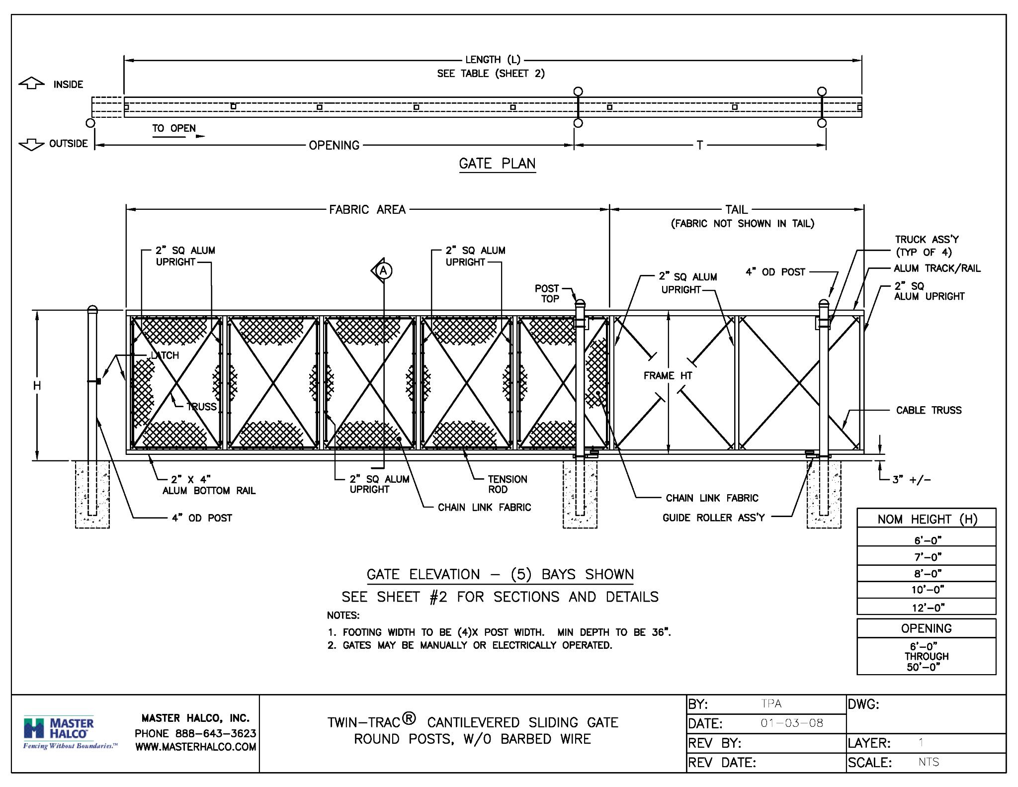
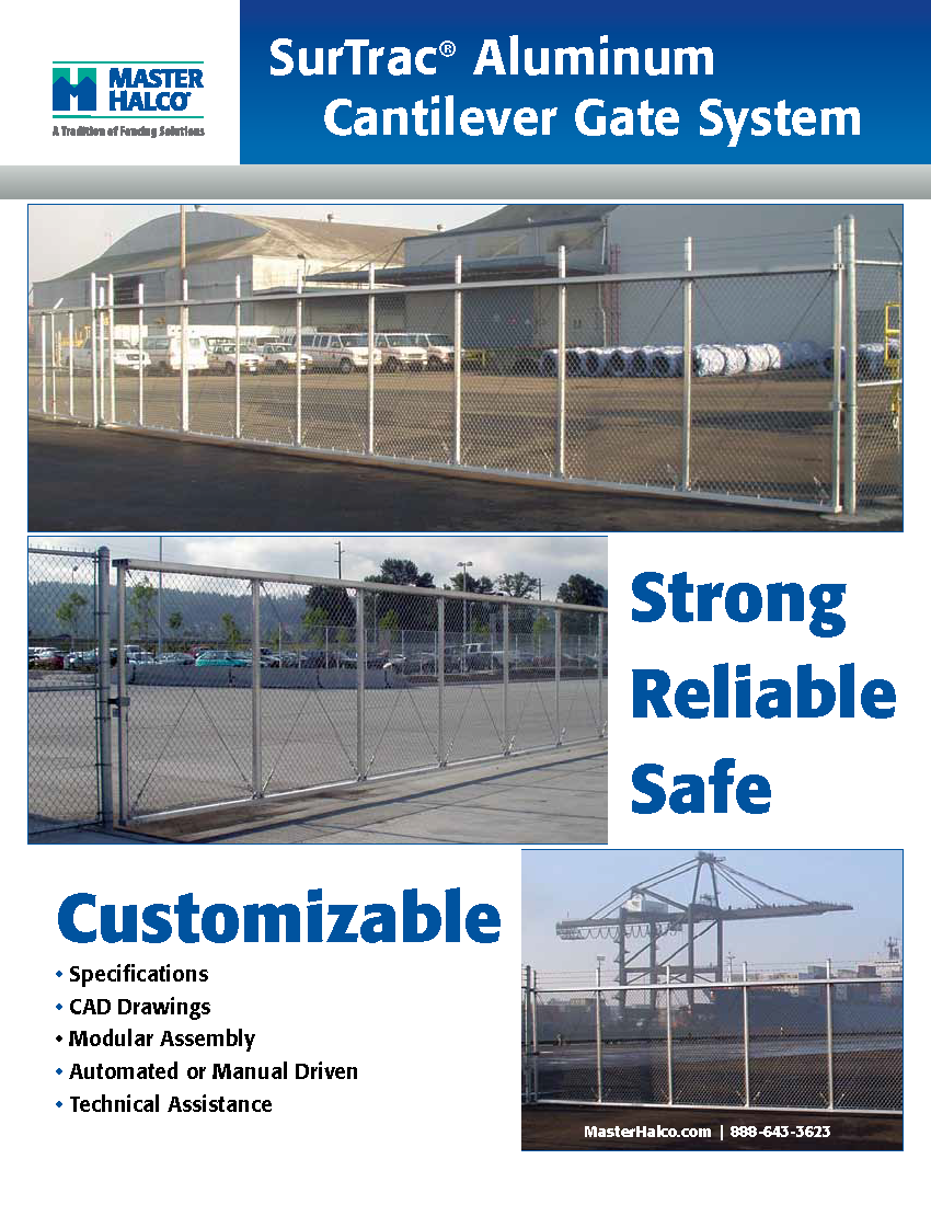
The Fast-Trac® and Twin-Trac® Aluminum Cantilever Gate Systems were developed and trademarked by QFB in the early 1990’s. QFB manufactures for Master Halco, Inc. who distributes these under the names of SurTrac® and TwinTracTM Cantilever Gates. If you are interested in purchasing a Cantilever Gate please contact Master Halco, Inc. directly. If would are interested in QFB installing a Cantilever Gate for your commercial project please contact us.
Fast-Trac® Aluminum Cantilever Gate Specifications
FENCE GATES
A. Aluminum Cantilever Slide Gates
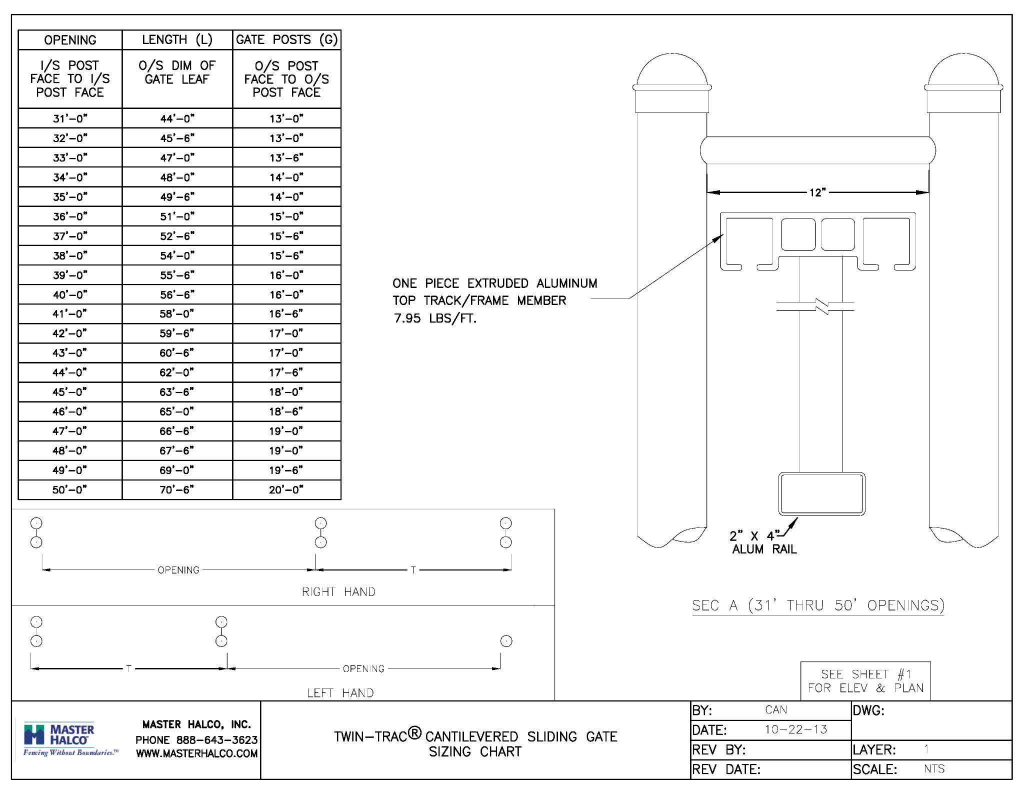
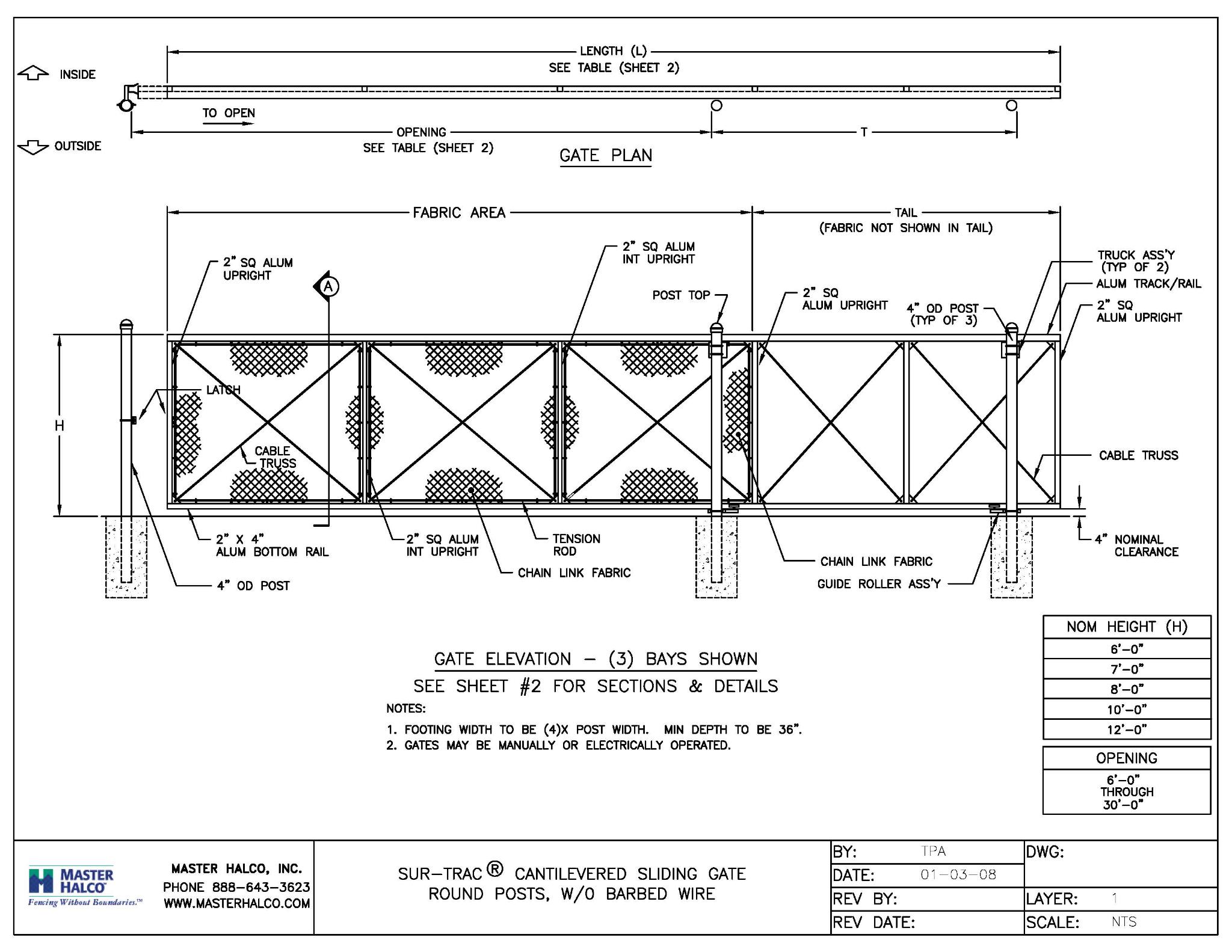
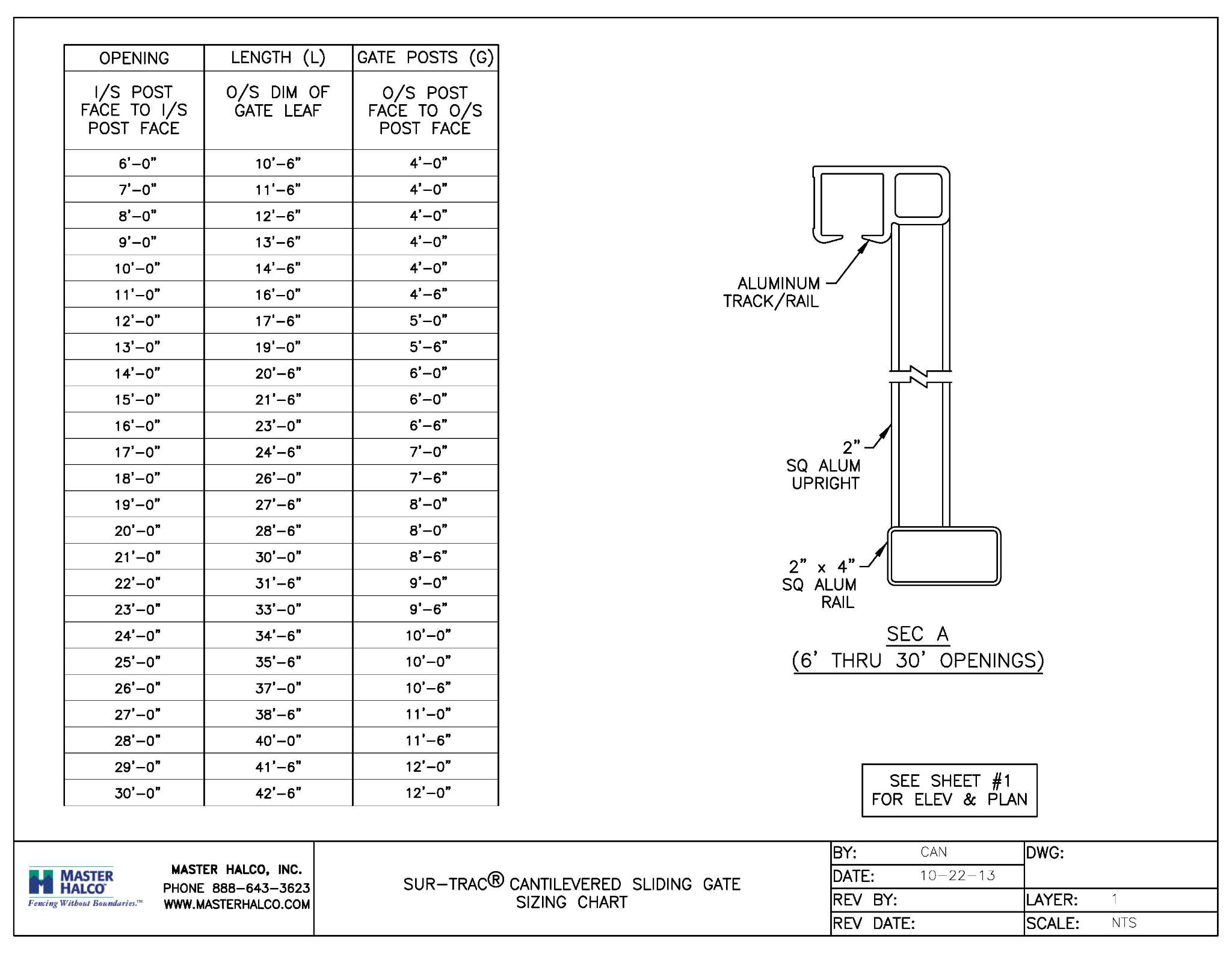
- Gate Frames: Shall be fabricated in accordance with ASTM F 1184, Class 2. Vertical frame members shall be 2 inch square aluminum, with a .125" wall thickness and weighing 1.1 lbs./ft. Bottom frame member shall be 2 inch x 4 inch aluminum, with a .125" wall thickness and weighing 1.7 lbs./ft. Top track/frame member shall be a one-piece aluminum extrusion, weighing a minimum of 4.6 lbs./ft. Aluminum alloy used shall be 6061-T6 only. Intermediate uprights shall be 2-inch square aluminum spaced equally at no more than 7 feet o.c. subdividing the gate frame into panels. All members shall be welded to form a rigid one-piece gate frame unit.
- Fabric Filler: Shall match fence and be attached to the frame by means of hook bolts. Fabric shall be attached between each internal upright with hook bolts spaced no more than 15 inches o.c. as recommended by the manufacturer.
- Trussing: Each bay shall be cross-trussed by means of 1/4" cable and adjustable turnbuckles bolted to corner gussets. Cable trussing will maintain the structural integrity of the gate while allowing for expansion and contraction of aluminum during various weather conditions.
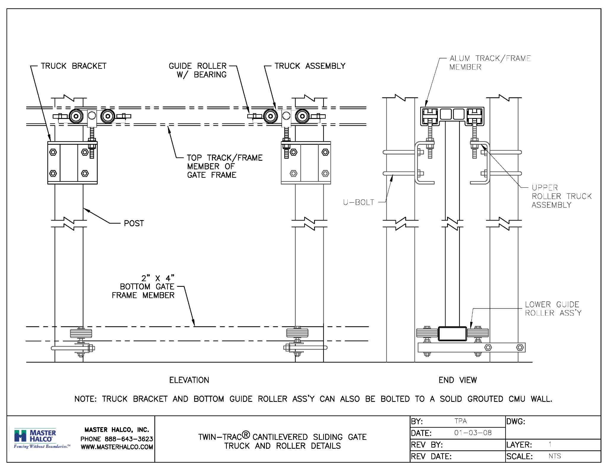
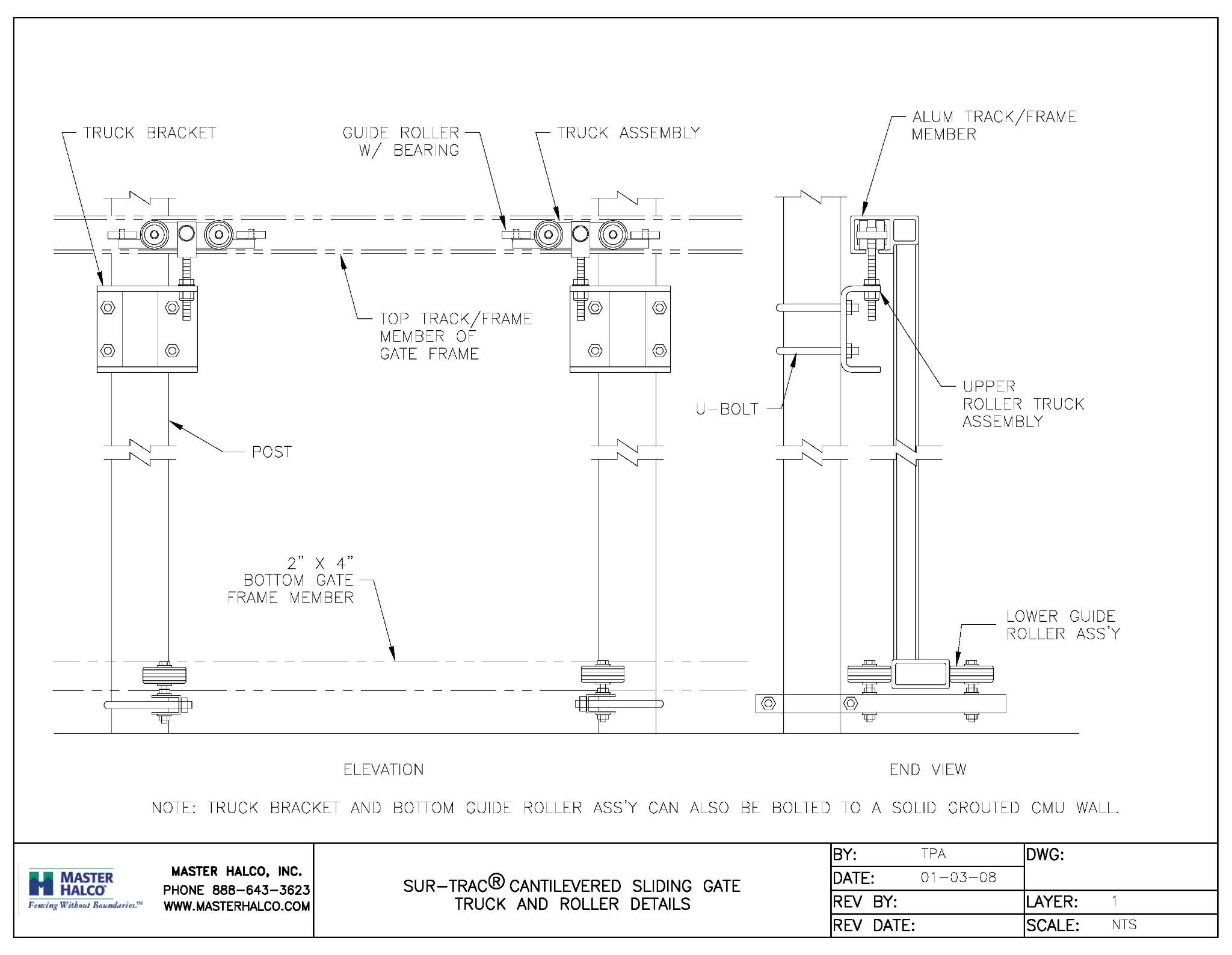
- Truck Assemblies: Shall be swivel type, zinc die cast, with six (6) factory sealed and lubricated ball bearing rollers. Four vertical rollers shall be 2 inches in diameter x 9/16-inch in width and two ball-bearing zinc plated steel side rollers to prevent lateral movement. Truck assemblies shall be mounted on post brackets using 7/8-inch diameter Clevis bolts with a 9/16-inch shank.
- Bottom Guide Wheel Assemblies: Two 3 inch diameter rubber wheels (one set) straddling the bottom horizontal gate rail shall be installed, one set on the gate post and one on the overhang post.
- Stop Bracket / End Plug: After gate has been installed, both ends of the combination track/frame member shall be closed off with a shock-absorbing block bolted through the frame. The bottom 2" x 4" horizontal rail shall also have both ends completely closed with aluminum plate that has been continuously welded into place at the factory.
- Hardware: Gate hangers, latches, brackets, guide assemblies and stops shall be steel, galvanized after fabrication. A positive latch device shall be provided with provisions for padlocking.
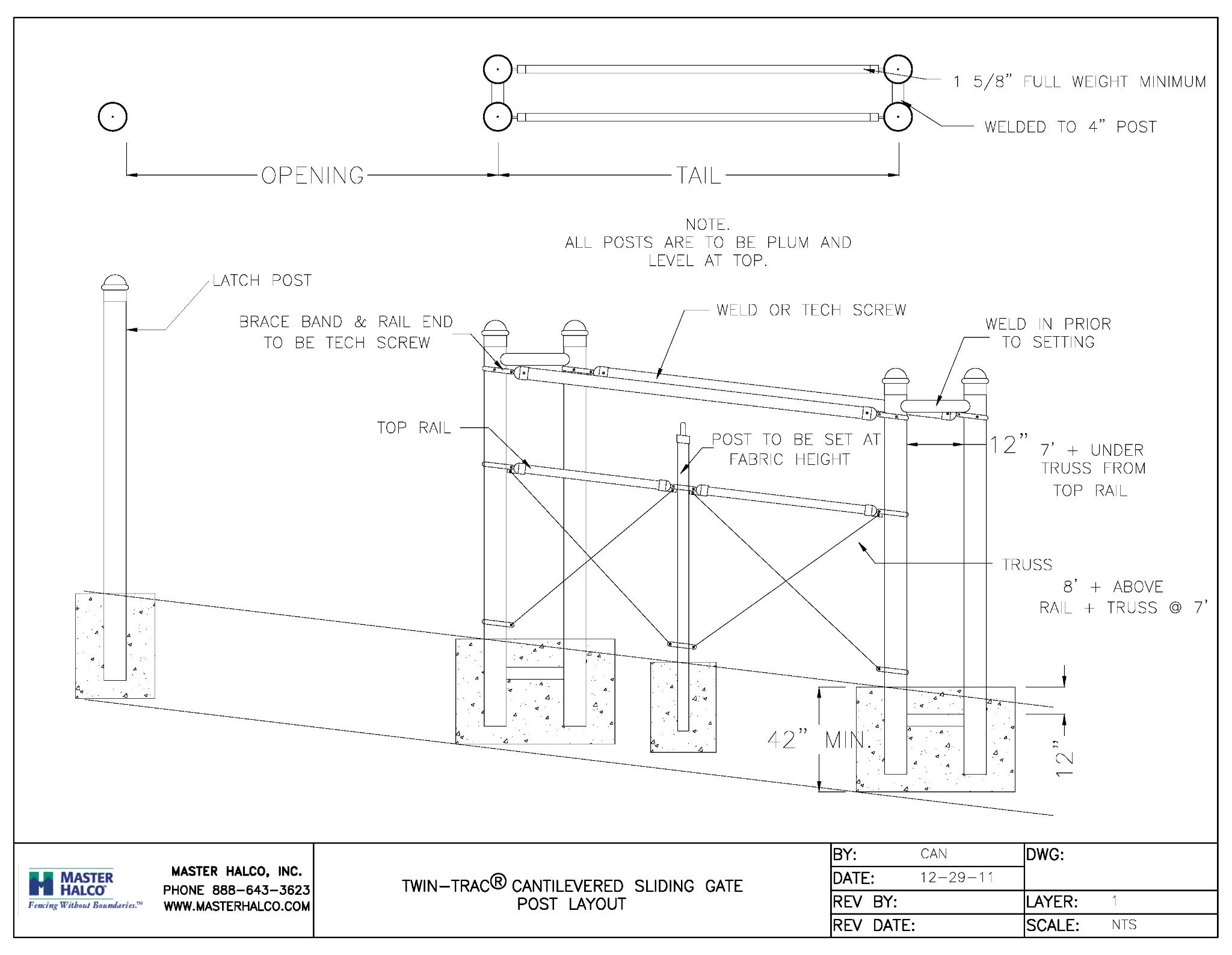
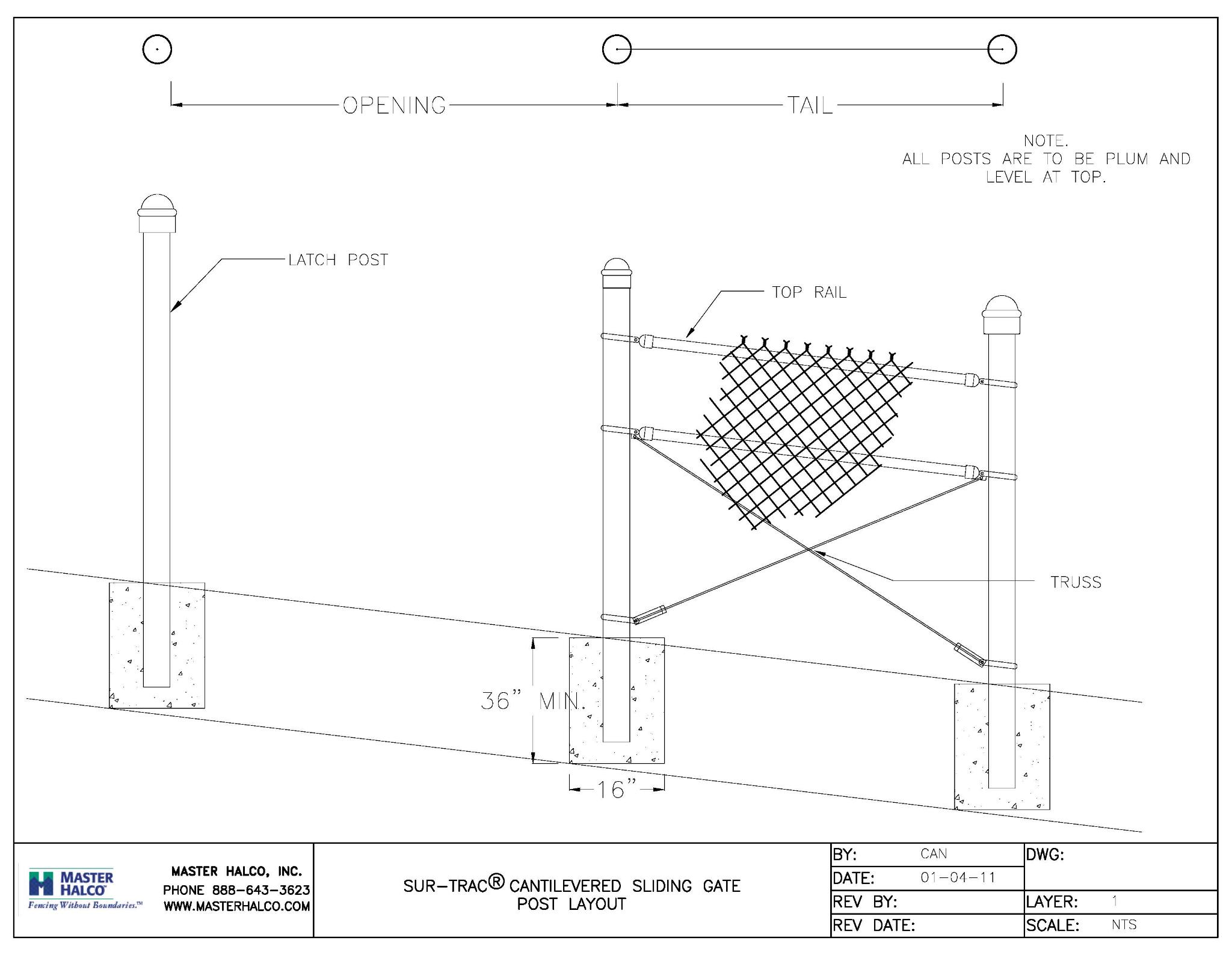
- Posts: Gate posts, latch posts and overhang posts shall be 4 inches O.D. Schedule 40 galvanized pipe set in 12 inches x 36 inches deep footings or as recommended by the manufacturer. Concrete shall be troweled and sloped to shed water away from the posts.
- Style: Style of gate frame shall be single, back-to-back or box frame, dictated by size of opening as recommended by manufacturer.
Single Gates Double Gates
- Single Up to 30 feet wide Up to 60 feet wide
- Back-to-Back Up to 40 feet wide Up to 80 feet wide
- Box Frame Up to 60 feet wide Up to 120 feet wide
- No wheels or supports at the bottom of the gate or guide track to keep clean
- Enclosed track at the top of the gate eliminates dangerous pinch points
- Three Standard Configurations
- Available in both chain link and decorative ornamental iron designs
- Available for openings from 6' to 120'
- Made in the USA
- Meets or Exceeds ASTM F-1184
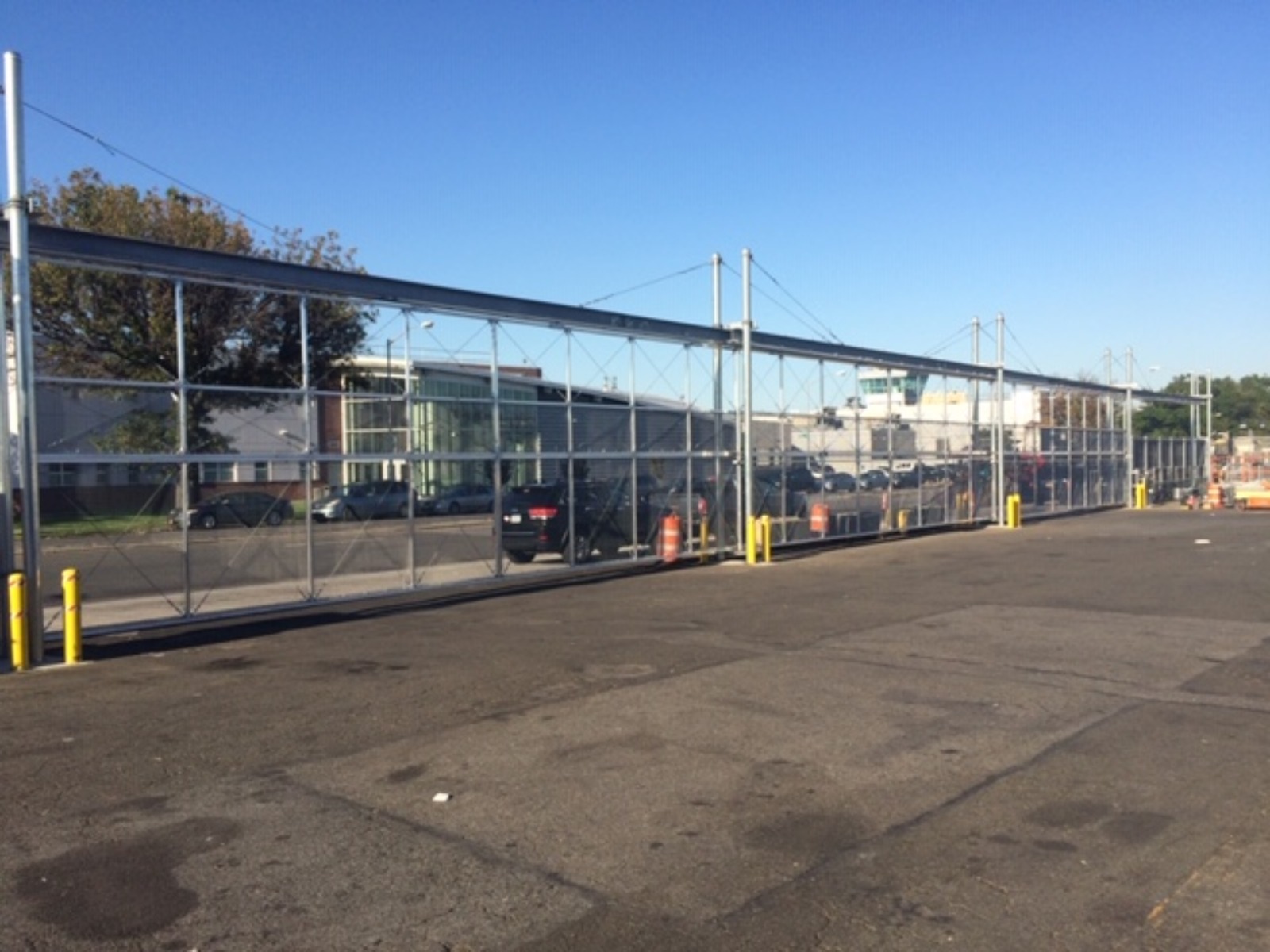
Master Halco Aluminum Cantilever Video
Quality Fence Builders, Inc. - Aluminum Cantilever Video
SurTrac® Cantilever
TwinTracTM Cantilever
